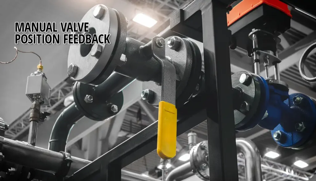
Manual valve position feedback answers a simple question: Is a hand-operated valve actually where the process needs it to be? Not every valve in a plant needs an actuator. Many are operated a few times a month, or a few times a year. They sit within reach of an operator, and turning a handle is quick, simple, and inexpensive.
But a valve that doesn’t need automation may still need monitoring. A drain valve left open, a bypass left closed, or a tank outlet in the wrong position can hold up a batch or start a pump against a closed line. The control system has no way of knowing unless something tells it.
What Manual Valve Position Feedback Actually Gives You
A limit switch on a hand-operated valve reports one thing: whether the valve is open or closed. The operator still turns the handle. The control system simply knows where the valve ended up.
Most switches use dry contacts, one for open and one for closed, wired directly into a PLC’s digital inputs. There’s no actuator, solenoid, or air supply involved.
That gives you two layers of indication:
- Local: handle orientation, plus a visual open/closed indicator on the switch, for anyone standing at the valve.
- Remote: an electrical signal to the PLC, HMI, or interlock, for everyone who isn’t.
The remote signal is what matters most. It turns an unknown into a confirmed status that the control system can act on. It can hold a permissive, flag an out-of-position valve, or log the change.
The valve itself doesn’t change. A standard manual ball valve or butterfly valve handles the flow. The switch adds the information. Assemblies that pair a manual valve with a factory-mounted limit switch keep manual operation simple and cost-effective while giving the control system the confirmation it needs.
Feedback alone doesn’t move the valve. If the process needs the valve to act on its own rather than just report, that’s a different conversation. We’ll get to it shortly.
Where Manual Valve Position Indication Earns Its Place
Manual valve position indication makes sense wherever a valve’s position affects what happens next, but the valve itself doesn’t need to move on its own.
Typical cases include:
- Permissives and interlocks. A pump shouldn’t start, or a batch shouldn’t begin, until a specific valve is confirmed in position. We’ve built assemblies for exactly this. In one, a limit switch on a sanitary ball valve confirms valve position before a pump offloads a truck. In another, a limit switch confirms a sanitary butterfly valve’s position before a batch fill begins.
- Infrequently operated valves. Bypass, drain, and tank outlet valves may sit untouched for weeks. When one is left in the wrong position, nobody notices until something downstream goes wrong.
- Valves out of the operator’s line of sight. These include valves behind equipment, overhead, or in another room. A remote signal saves a walk and removes the guesswork.
- Flow path lineups. On manifolds or diverting arrangements, such as a manual 3-way diverter ball valve routing product between two tanks, a feedback signal confirms the flow path before the transfer begins.
The common thread is that someone or something downstream is relying on the valve’s position. If the answer to “who needs to know?” goes beyond the person standing at the valve, feedback is worth specifying.
Manual vs. Automated Valve: Signs It’s Time to Add an Actuator
The deciding question is simple: does the system only need to know where the valve is, or does it need to move it?
If it only needs to know, a manual valve with a limit switch is usually enough. Monitoring alone tends to fit when:
- The valve changes position infrequently.
- An operator is nearby when a change is needed.
- A short delay between the decision and the move is acceptable.
- A person, not the control system, should make the call.
Once the system needs to act, feedback alone falls short. Automation is the better fit when:
- The valve cycles often enough that manual operation costs real labor time or invites mistakes.
- It must open or close on a remote command, or respond to a shutdown signal.
- The location is unstaffed, hard to reach, or unsafe to approach during a process upset.
- The valve is large enough that operating it by hand, especially through a gear operator, takes real effort.
- The process depends on consistent, repeatable timing from one cycle to the next.
- The application calls for throttling rather than simple open/close.
Borderline cases often come down to cost. A manual valve with a limit switch costs less upfront and needs no air supply or actuator power at the valve. But if operators walk out to the same valve several times a shift, that labor adds up. In those cases, an actuated valve fitted with the same type of limit switch handles both jobs. It moves the valve and confirms where it went.
If automation is likely down the road but not justified today, there’s a middle path. We’ll cover it in the specifying section.
Position Feedback Confirms. It Doesn’t Isolate.
Position feedback often comes up alongside lockout/tagout, and it has a role there. But it’s worth being precise about that role.
A limit switch confirms a valve’s position. It doesn’t keep it there. Under OSHA’s lockout/tagout standard (29 CFR 1910.147), isolating a line means physically securing the energy-isolating device, often the valve itself, so it can’t be moved while work is under way. The stakes are real. OSHA estimates that compliance with the standard prevents about 120 fatalities and 50,000 injuries each year.
For manual valves that serve as isolation points, that means pairing feedback with a lockable handle. Many manual valves are available with locking levers that accept a padlock. The lock holds the valve in position. The switch confirms that position to the control system, and to everyone relying on it.
Feedback supports the verification step. It doesn’t replace the lockout itself, or the checks your procedure requires before work begins.
How to Specify a Manual Valve Limit Switch
A manual valve limit switch spec doesn’t need to be long, but it does need to be complete. Gaps tend to surface at commissioning, not before. Cover these points:
- Mounting interface. A valve with an ISO 5211 mounting pad makes the switch bracket simple. This is the middle path I mentioned earlier: the same pad accepts an actuator later, without replacing the valve.
- Switch technology. Mechanical or proximity, chosen by cycle rate and environment. Our position feedback Q&A covers the trade-offs.
- Outputs. Open, closed, or both. Interlocks usually need both.
- Electrical compatibility. Match the switch’s voltage and current rating to the PLC input card.
- Enclosure. NEMA 4X covers most washdown and outdoor installations. In hazardous locations, the enclosure must match the site’s Class/Division classification.
- Lockout provision. Specify a locking lever if the valve serves as an isolation point.
Our valve limit switches include mechanical and proximity options across several enclosure ratings, so the choice comes down to the application.
Finally, decide how the assembly comes together:
- Factory-built: the switch is mounted, cams are set to open and closed, and the assembly is tested before it ships.
- Field retrofit: existing valves can take a switch with the right bracket. We’ve fabricated custom mounting kits for valves already in service.
Talk to Us About Your Application
Not sure whether a valve needs monitoring, full automation, or something in between? Talk with one of Assured Automation’s valve automation experts. We’ll help you specify the right assembly for your process.

General Manager